After removing the controller board from the back of the battery compartment, I began documenting wires and board traces to determine what made the trap tick. This particular mousetrap was purchased in Dec, 2012. I also have one that was purchased awhile back that operates the same as this one, however, I haven't taken it apart to see if the components are different. Keep in mind, if you do this mod at a later date, things may have changed.
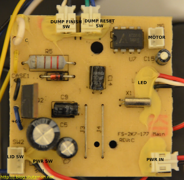
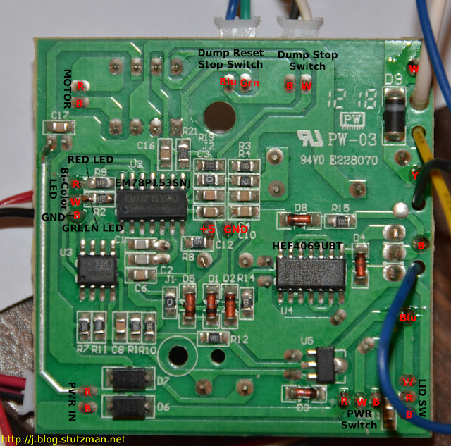
The controller board of the mousetrap has components on both sides as shown below:
The MCU is the 8-bit EM78P153SNJ. It is responsible for running the predefined program for the mousetrap. Based on my observations and various trap exercises the system operates like this:
In the center of the "back" of the board I probed a good solder point to get the needed +5 and GND for my design, which I will talk about in the next post....
-----
Resources:
1. EM78P153SNJ data sheet (140-00275-0-EM78P153S.pdf)
2. The type of Bi-color LEDs used here is the type consists of two dies with separate leads for both dies and another lead for common cathode, so that they can be controlled independently.
The controller board of the mousetrap has components on both sides as shown below:
 |
| front of board with connectors |
 |
| "back" of the controller board labeled with the wire color in red text |
- When the power switch is turned on the green LED momentarily turns on for about 1 second.
- As the LED turns off, the electronic chamber makes a buzzing sound (testing or precharging) for about 3 seconds
- Next the motor attempts to rotate the chamber to rest position (if it is unable to it will rotate the chamber to dump position and then back to rest position. Failing that, the red LED will blink and the trap will be inoperative until the obstruction is removed and the trap is power cycled)
- When a mouse enters the chamber, the chamber will begin discharging as follows: 20 seconds of electrical current, 5 seconds of rest, another 20 seconds of electrical current, then finally the chamber will dump and the trap resets for the next mouse.
- Once the trap has dispatched a mouse, the green LED will blink notifying the user that there is a reason to empty the drawer.
- After the trap has gone through 10 iterations, both the green and red LEDs blink in unison showing an amber color to the user indicating the drawer is full and the trap will be inoperative until it is reset.
- Red-White continuity when lid closed
- Blk-White continuity when lid open
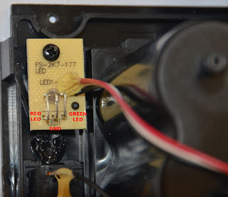
The remote LED board will be used to vampire the signal from the trap:
 |
| LED board shown with annotations |
-----
Resources:
1. EM78P153SNJ data sheet (140-00275-0-EM78P153S.pdf)
2. The type of Bi-color LEDs used here is the type consists of two dies with separate leads for both dies and another lead for common cathode, so that they can be controlled independently.
No comments:
Post a Comment