Sunday, December 30, 2012

Wireless Mousetrap

As I stated in the first post, the Multi-Kill traps are great when you have lots of mice to deal with. The only issue is that after awhile I stop checking them as diligently and this becomes a rather smelly problem. Enter XBee!

XBee's are neat little wireless modules that handle the dirty work of signaling. I use the Series 1 XBee with the wire antenna. It is very easy to setup, which allows the remote XBee to cyclically send data to the receiver base XBee.

I use Linux (namely Ubuntu) for pretty much everything these days. Unfortunately the XBee X-CTU application is Windows only. However, it is known to work with Wine and in my experience it works very good. (Here is a guide for setting up the X-CTU in Ubuntu).

Here is the plan:
  1. Make the smallest amount of changes to the mousetrap
  2. Use the least amount of power as necessary on the remote transmitter XBees
  3. Leverage Adafruit's tweet-a-watt project for remote XBee hardware (with some modifications)
This post will focus on the hardware modification to integrate the remote (transmitting) XBee into the mousetrap. I determined that the best place to acquire the +5 and GND where on the back side of the controller board. I used +5V because the adafruit module I 'm using has a built-in 3.3V regulator. Here are a few pictures showing the install.

The tweet-a-watt uses a few more components. I removed the large capacitor.
orange wire to AD0 and yellow wire to AD4 (shown with 10K resistors)
Using a bit of shrink tubing solder the yellow wire to AD0 and the orange wire to AD4 of the XBee carrier board shown above. Once connected, solder the I soldered the wires as shown below.

Yellow wire to the Green LED lead, Orange wire to the Red LED Lead
Back of board showing with White wire to +5 and Black wire to GND, this supplies XBee
Completed mod
Once the mod was completed I positioned it as shown above. I used a small amount of 2-sided tape to stick it the top of the battery compartment. The board fits between the back of the motor and the side of the trap. I drilled a small hole in the top of the trap for the XBee green led to protrude through the front. This is pictured below:

Next up I will talk about the programming and data collection...

X-CTU on Ubuntu

Digi's X-CTU is a Windows only application. However, it can be made to run quite well under Linux. This is how I set it up under Ubuntu 12.10. (I used Google to find the answers to many of my questions. Thanks Lazyweb.)

Linux requires users to have permissions to access hardware. In this case the user needs to be a member of the dialout group. Do the following as the user you intend to run X-CTU under:
    sudo adduser ${USER} dialout
Note: You will have to logout and login for the changes to be fully realized.

First get wine:
   sudo apt-get install wine

Then symlink the Linux serial devices to:
   ln -s /dev/ttyUSB0 ~/.wine/dosdevices/com5
   ln -s /dev/ttyUSB1 ~/.wine/dosdevices/COM5
   ln -s /dev/ttyUSB0 ~/.wine/dosdevices/com6
   ln -s /dev/ttyUSB1 ~/.wine/dosdevices/COM6
Note: I used both uppercase and lowercase "COM" because it seemed that the lowercase worked when I was troubleshooting.

Go to: http://www.digi.com/support/productdetail?pid=3661 and click on "General Diagnostics, Utilities and MIBs" which will reveal the download for X-CTU. Download X-CTU (I used XCTU ver. 5.2.7.5):
    http://ftp1.digi.com/support/utilities/40003002_B.exe

Make the file executable:
    chmod 755 40003002_B.exe

Open X-CTU installer with wine program loader by right-clicking on the file in Nautilus and choosing: Open with Wine program loader. Install application.

Selecting Serial Port

Every time you run X-CTU you will need to add the user com port. I used '5' below for COM5, which represented /dev/ttyUSB0 on my machine:


You must select the COM port before the Test / Query operation will work

Updating firmware

One of the things that doesn't work in X-CTU under Wine is the auto firmware download from the web. However, when you download the files manually and extract them to the correct location, you can update the XBee just like under Windows.

Navigate to: http://www.digi.com/support/productdetail?pid=3661 and download the latest firmware. I used "XBee / XBee-PRO ZB firmware ver. 2xA7" which was the 82001817_G.zip file (Dec 2012). Then copy to the update directory:
    cp ~/.wine/drive_c/Program\ Files\ \(x86\)/Digi/XCTU/update/

Now from within X-CTU, add the updates using the Modem Configuration tab and clicking on "Download new versions..." button. Then click on the "File..." button and choose the zip file under the update directory. Restart X-CTU and the new firmware should be available.

Updating XBee Firmware

To update the XBee select the correct serial port and click on the Modem Configuration tab, then check the "Always update firmware" check box. Next select the correct Modem, Function Set, and Version (It appears that the list of versions are ordered in reverse, whereas the newest firmware is listed first). Once selected, click on the "Write" button. See screenshot below:


Friday, December 28, 2012

Victor Multi-Kill Controller

After removing the controller board from the back of the battery compartment, I began documenting  wires and board traces to determine what made the trap tick. This particular mousetrap was purchased in Dec, 2012. I also have one that was purchased awhile back that operates the same as this one, however, I haven't taken it apart to see if the components are different. Keep in mind, if you do this mod at a later date, things may have changed.

The controller board of the mousetrap has components on both sides as shown below:
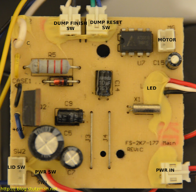
front of board with connectors
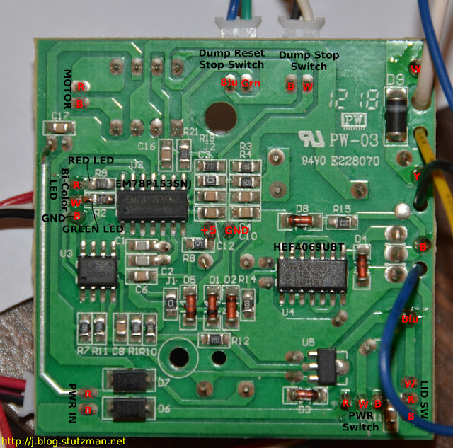
"back" of the controller board labeled with the wire color in red text
The MCU is the 8-bit EM78P153SNJ. It is responsible for running the predefined program for the mousetrap. Based on my observations and various trap exercises the system operates like this:
  1. When the power switch is turned on the green LED momentarily turns on for about 1 second.
  2. As the LED turns off, the electronic chamber makes a buzzing sound (testing or precharging) for about 3 seconds
  3. Next the motor attempts to rotate the chamber to rest position (if it is unable to it will rotate the chamber to dump position and then back to rest position. Failing that, the red LED will blink and the trap will be inoperative until the obstruction is removed and the trap is power cycled)
  4. When a mouse enters the chamber, the chamber will begin discharging as follows: 20 seconds of electrical current, 5 seconds of rest, another 20 seconds of electrical current, then finally the chamber will dump and the trap resets for the next mouse.
  5. Once the trap has dispatched a mouse, the green LED will blink notifying the user that there is a reason to empty the drawer.
  6. After the trap has gone through 10 iterations, both the green and red LEDs blink in unison showing an amber color to the user indicating the drawer is full and the trap will be inoperative until it is reset.
Note: the lid switch is in series with the toggle power switch so if the lid is open there is no power to the controller board. From a wire continuity perspective:

  • Red-White continuity when lid closed
  • Blk-White continuity when lid open
The remote LED board will be used to vampire the signal from the trap:
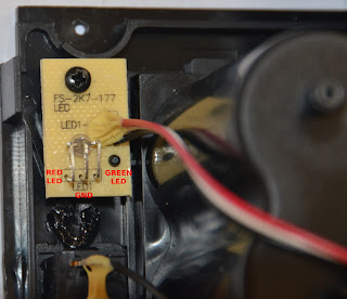
LED board shown with annotations
In the center of the "back" of the board I probed a good solder point to get the needed +5 and GND for my design, which I will talk about in the next post....

-----
Resources:
1. EM78P153SNJ data sheet (140-00275-0-EM78P153S.pdf)
2. The type of Bi-color LEDs used here is the type consists of two dies with separate leads for both dies and another lead for common cathode, so that they can be controlled independently.

Victor Multi-Kill Teardown

The mouse trap is very easy to disassemble. There are four screws on the front around the battery door, one screw on the front right holding the top down, and then two screws at the back along the top of the top cover.

In order to pull the battery compartment out of the trap, the lid switch lead needs to be unplugged from the back of the circuit board. NOTE: Victor did an excellent job making this repairable. Each major component is connected to the board with a plug and socket NOT soldered to board. Kudos.

Here are some close up pictures of the various parts of the trap:

Chamber the mouse goes through starting at the back left.

The circuit board is screwed to the back of the battery compartment.
The lower left shows a small PCB where the bi-color red/green LED is located.
The motor which dumps the mouse after it has expired

Several wires enter the bottom of the chamber. I did not investigate them, although one is for high voltage capacitor charging!

Next up, identifying the main components of the circuit board and the design for getting this information to an email.

Victor Multi-Kill

So this blog has been dormant for awhile and my son and I have been working on a project. So what better way to bring this tired blog back from the dead!

I've been using the Victor Multi-Kill for the past year or so. It works very well. It uses a humane killing mechanism that electrocutes the mouse when it enters the chamber. The mouse is dispatched quickly, then it is disposed in the collection drawer. The drawer will hold up to 10 mice between resets. Over the last year the only problem I've had with the trap is that sometimes we forget to check it for mouse remains (in the summer time that is a serious problem). Below are a few images of the unit:


My plan is to modify this machine to send an email anytime a mouse is killed or if there are any issues needing attention.

Stay Tuned...

-----
Resources:
1. The Victor Multi-kill is available at http://www.victorpest.com/store/mouse-control/m260
2. Peanut butter seems to be the best bait.