Wednesday, March 27, 2013

Raspberry Pi Mouser

I've taken a bit of a hiatus from the mousetrap project I began a few months ago. There were a couple of reasons for it, one of which was my disappointment with the range of the XBee connection, the other was short battery life of the traps. I believe I have now solved both of those problems.

Raspberry Pi
I've had issues with other 2.4 GHz transceivers in my home. Perhaps it is a noisy environment, or maybe it is walls lined with heavy metals. For whatever reason, my receiver would report very low RSSI readings from my mousetraps' transmitters when the transmitters were in the attic and garage and the receiver was in the office. In fact, some reports never made it to the receiver causing the logic of the software to timeout and set the mousetrap as offline.

I decided I needed to move the receiver to a more central location in my home (I also had to do the same thing with my Wifi AP). However I didn't want to drag a laptop or PC with it, so I opted to use a Raspberry Pi (raspi) board. The end result looks like this:
RaspberryPi in a case with XBee

The raspi has a nasty USB issue that gives me grief every time I attempt to use the USB ports for anything more than keyboards or mice. In fact, my adafruit usb to XBee adapter did not work when plugged into the raspi. I decided that if I was going to use the raspi I would need to use the built-in serial headers and enclose it inside a nice package. The plan was to place this somewhere central and I didn't want a bag of parts to be just hanging out.

My raspi Bill of Materials (BoM):
  1. RaspberryPi Model B 512MB RAM
  2. Slice Of Pi Breakout Board
  3. pIO - microSD card adapter
  4. Stealth Black Case from ModMyPi
These items are all available at http://www.modmypi.com (no disclosure needed, just a happy customer) as well as other places around the web. The nice thing about the breakout board is that it comes with the PCB traces and headers required for the raspi to communicate with the XBee. The only thing I needed to do was solder the main header which plugs into the raspi and the smaller headers used for the XBee.
Components of the Raspberry Pi Mousetrap
Take a close look at the next image. Notice how the breakout board sits at an angle:
Raspberry Pi with Breakout Board

Here is the point that I want to make: The case from ModMyPi is very well done and completes the setup very nicely. However with the extra standoffs from the XBee module it will not snap together completely. I debated for about 30 minutes if I was willing to solder the XBee directly to the breakout board, but ultimately decided against it because this is still a "project" and I often hook the XBees to X-CTU for configuration. If I had soldered the XBee down, I wouldn't be able to connect it to the special breakout board which the XBees plug in to for programming.

To get everything to fit, I first ensured that as much of the breakout board as possible was as low as possible, which is why I soldered the header at an angle. Next, the ABS plastic used in the case was pretty thick and I was able to grind out enough material on the underside of top so that the XBee board no longer kept the case from snapping together. Here is picture of the underside of the top of the case:
The arrow shows the hole that was drilled to allow the XBee antenna to protrude through the top of the case. The ground out area is where I used a Dremel tool to carve out enough material for the case to snap together. It isn't very pretty on the underside, but you'd never know it looking from the top! It would be nice if ModMyPi offered an extended case where the top was taller, then I would not have had this issue.

Here are some pictures of the final product in operation (notice the pIO microSD adapter shown in the first picture):


Battery Life
It turns out that XBees use a bit of power! Even using them to wake at intervals uses more power than I expected. I've revamped the settings to poll the Victor traps less frequently, which gives much longer battery life (still testing this). In the next entry, I will discuss and post the final python code, XBee settings, and raspi options needed to be able to use the built in serial headers in user code.

Stay Tuned!

Monday, March 18, 2013

Aeroquad Multicopter

One of my latest areas of interest are multi-rotor flying vehicles. I've been interested in them for awhile, but never enough to get serious. Then last year I saw a video of a quadcopter on some website showing someone FPV (First Person View) flying around in Paris. It renewed my interested once again. This time, however, I was determined to get into the hobby.

My philosophy on hardware and software is to look for something that isn't closed. This means that I don't want to spend my money or time on a platform that is controlled by a single entity with no way to improve the platform should that single entity decides to quit. I used my best Google Foo and stumbled upon AeroQuad (http://aeroquad.com). This is a project that was started by an individual but has quite a following of folks working on various parts of the platform as part of their hobby. The software and hardware are both opensource!

I decided to go with the Typhoon ARF (almost ready to fly) kit because I'm new to this hobby and I didn't feel like sourcing everything myself. The ARF kit includes everything you need except for transmitter and batteries, so it doesn't take long to get ready to fly.

Here are a couple of pictures of the build in progress:


Although this hobby can be a bit pricey, it was a fun and easy build. Stay tuned for flying pictures!

Wednesday, January 2, 2013

Hexbright Flashlight

I thought I take a break out of posting about my mousetrap mod and post a bit about the HexBright flashlight. This flashlight started as a Kickstarter project, which is now something you can buy. I first bought one just to play around with it. After I got one, I was so impressed with the build quality, brightness and lens that I bought 2 more! To get yours visit http://www.hexbright.com (I was informed the price will be going up soon once it hits distributors).


What makes this flashlight so special to me personally is that it is open source hardware. If you know me, you'll know that I'm an OSS/H junky. The MCU that the flashlight uses is Arduino compatible. This means that you can modify the firmware in the Arduino IDE with standard Arduino libraries and upload it to the flashlight like you would do with any of your Arduino projects. How cool is that? I've made some changes to the stock firmware and published them on https://github.com/jaebird/HexBrightFLEX/. There are several of us fairly active on github "improving" the stock firmware with things that we really want. I added SOS mode and a quick power off method where long-pressing the button in any mode turns off the flashlight so you don't have to cycle through each one. However, you can do whatever you want with it.

Here are some quick specs:

  • 500 Lumens (using CREE XM-L U2 LED)
  • Aluminum construction (very solid)
  • PMMA TIR Lens (instead of using a reflective mirror that can get dirty or corrode)
  • USB rechargeable and programmable
  • Arduino Compatible
  • Open Source
Dare I say this unit seems as good as any of those "tactical" flashlights you might be using.

Some of my non-Software Mods


Filter Mod


Amazon.com is selling a RED filter that mostly works with the HexBright FLEX. http://www.amazon.com/gp/product/B0051F7UF2

The bezel of the HexBright FLEX is 1 1/4" in diameter. The Olight M20 Red Filter is 1 7/16", so the filter is just a tad too big to stay on the flashlight. So I took out my hot glue gun and laid a bead of glue on the inside of the filter to make the diameter smaller. Now the filter stays on really well with very little light bleeding out the back of the filter.

Tip: Use a moistened finger to spread the hot glue along the entire inside circumference.

Battery Mod


I have some EagleTac 3100mAh 3.7 18650 Li-ion batteries that I picked up from (http://goinggear.com/eagletac-protected-18650-3100-mah-rechargeable-3-7v-li-ion-battery.html).

They are IC protected with over charge protection from 4.2-4.25V and over discharge protection from 2.7-2.9V and short protection between 4A-6A. They charge and work fine with the HexBright FLEX. I have not had time to test them for how much longer the flashlight will run with this battery. EagleTac also has a 3400 mAh battery available.


Note: I have no relationship to HexBright, just a very satisfied customer... and hacker!

Sunday, December 30, 2012

Wireless Mousetrap

As I stated in the first post, the Multi-Kill traps are great when you have lots of mice to deal with. The only issue is that after awhile I stop checking them as diligently and this becomes a rather smelly problem. Enter XBee!

XBee's are neat little wireless modules that handle the dirty work of signaling. I use the Series 1 XBee with the wire antenna. It is very easy to setup, which allows the remote XBee to cyclically send data to the receiver base XBee.

I use Linux (namely Ubuntu) for pretty much everything these days. Unfortunately the XBee X-CTU application is Windows only. However, it is known to work with Wine and in my experience it works very good. (Here is a guide for setting up the X-CTU in Ubuntu).

Here is the plan:
  1. Make the smallest amount of changes to the mousetrap
  2. Use the least amount of power as necessary on the remote transmitter XBees
  3. Leverage Adafruit's tweet-a-watt project for remote XBee hardware (with some modifications)
This post will focus on the hardware modification to integrate the remote (transmitting) XBee into the mousetrap. I determined that the best place to acquire the +5 and GND where on the back side of the controller board. I used +5V because the adafruit module I 'm using has a built-in 3.3V regulator. Here are a few pictures showing the install.

The tweet-a-watt uses a few more components. I removed the large capacitor.
orange wire to AD0 and yellow wire to AD4 (shown with 10K resistors)
Using a bit of shrink tubing solder the yellow wire to AD0 and the orange wire to AD4 of the XBee carrier board shown above. Once connected, solder the I soldered the wires as shown below.

Yellow wire to the Green LED lead, Orange wire to the Red LED Lead
Back of board showing with White wire to +5 and Black wire to GND, this supplies XBee
Completed mod
Once the mod was completed I positioned it as shown above. I used a small amount of 2-sided tape to stick it the top of the battery compartment. The board fits between the back of the motor and the side of the trap. I drilled a small hole in the top of the trap for the XBee green led to protrude through the front. This is pictured below:

Next up I will talk about the programming and data collection...

X-CTU on Ubuntu

Digi's X-CTU is a Windows only application. However, it can be made to run quite well under Linux. This is how I set it up under Ubuntu 12.10. (I used Google to find the answers to many of my questions. Thanks Lazyweb.)

Linux requires users to have permissions to access hardware. In this case the user needs to be a member of the dialout group. Do the following as the user you intend to run X-CTU under:
    sudo adduser ${USER} dialout
Note: You will have to logout and login for the changes to be fully realized.

First get wine:
   sudo apt-get install wine

Then symlink the Linux serial devices to:
   ln -s /dev/ttyUSB0 ~/.wine/dosdevices/com5
   ln -s /dev/ttyUSB1 ~/.wine/dosdevices/COM5
   ln -s /dev/ttyUSB0 ~/.wine/dosdevices/com6
   ln -s /dev/ttyUSB1 ~/.wine/dosdevices/COM6
Note: I used both uppercase and lowercase "COM" because it seemed that the lowercase worked when I was troubleshooting.

Go to: http://www.digi.com/support/productdetail?pid=3661 and click on "General Diagnostics, Utilities and MIBs" which will reveal the download for X-CTU. Download X-CTU (I used XCTU ver. 5.2.7.5):
    http://ftp1.digi.com/support/utilities/40003002_B.exe

Make the file executable:
    chmod 755 40003002_B.exe

Open X-CTU installer with wine program loader by right-clicking on the file in Nautilus and choosing: Open with Wine program loader. Install application.

Selecting Serial Port

Every time you run X-CTU you will need to add the user com port. I used '5' below for COM5, which represented /dev/ttyUSB0 on my machine:


You must select the COM port before the Test / Query operation will work

Updating firmware

One of the things that doesn't work in X-CTU under Wine is the auto firmware download from the web. However, when you download the files manually and extract them to the correct location, you can update the XBee just like under Windows.

Navigate to: http://www.digi.com/support/productdetail?pid=3661 and download the latest firmware. I used "XBee / XBee-PRO ZB firmware ver. 2xA7" which was the 82001817_G.zip file (Dec 2012). Then copy to the update directory:
    cp ~/.wine/drive_c/Program\ Files\ \(x86\)/Digi/XCTU/update/

Now from within X-CTU, add the updates using the Modem Configuration tab and clicking on "Download new versions..." button. Then click on the "File..." button and choose the zip file under the update directory. Restart X-CTU and the new firmware should be available.

Updating XBee Firmware

To update the XBee select the correct serial port and click on the Modem Configuration tab, then check the "Always update firmware" check box. Next select the correct Modem, Function Set, and Version (It appears that the list of versions are ordered in reverse, whereas the newest firmware is listed first). Once selected, click on the "Write" button. See screenshot below:


Friday, December 28, 2012

Victor Multi-Kill Controller

After removing the controller board from the back of the battery compartment, I began documenting  wires and board traces to determine what made the trap tick. This particular mousetrap was purchased in Dec, 2012. I also have one that was purchased awhile back that operates the same as this one, however, I haven't taken it apart to see if the components are different. Keep in mind, if you do this mod at a later date, things may have changed.

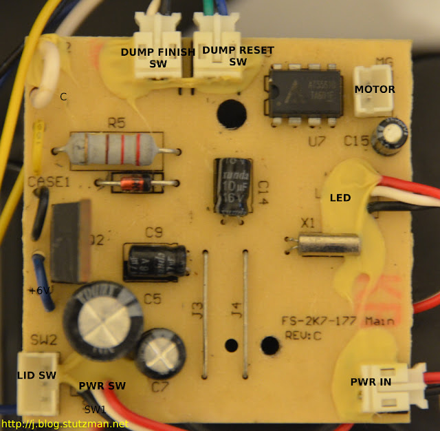
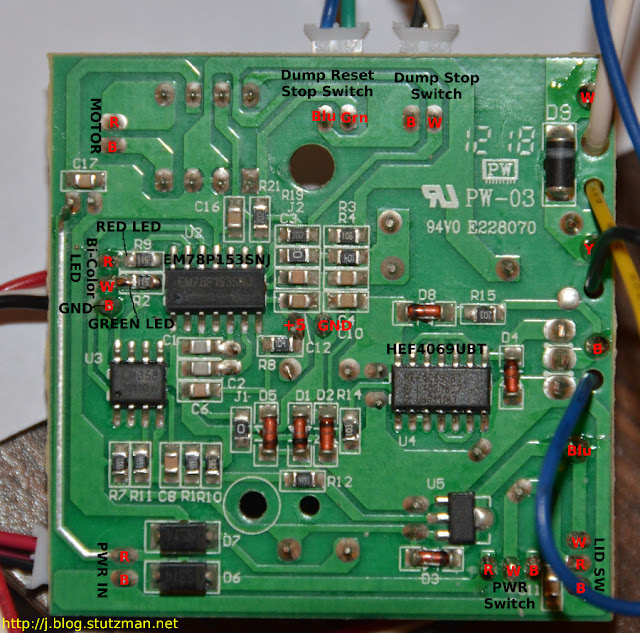
The controller board of the mousetrap has components on both sides as shown below:
front of board with connectors
"back" of the controller board labeled with the wire color in red text
The MCU is the 8-bit EM78P153SNJ. It is responsible for running the predefined program for the mousetrap. Based on my observations and various trap exercises the system operates like this:
  1. When the power switch is turned on the green LED momentarily turns on for about 1 second.
  2. As the LED turns off, the electronic chamber makes a buzzing sound (testing or precharging) for about 3 seconds
  3. Next the motor attempts to rotate the chamber to rest position (if it is unable to it will rotate the chamber to dump position and then back to rest position. Failing that, the red LED will blink and the trap will be inoperative until the obstruction is removed and the trap is power cycled)
  4. When a mouse enters the chamber, the chamber will begin discharging as follows: 20 seconds of electrical current, 5 seconds of rest, another 20 seconds of electrical current, then finally the chamber will dump and the trap resets for the next mouse.
  5. Once the trap has dispatched a mouse, the green LED will blink notifying the user that there is a reason to empty the drawer.
  6. After the trap has gone through 10 iterations, both the green and red LEDs blink in unison showing an amber color to the user indicating the drawer is full and the trap will be inoperative until it is reset.
Note: the lid switch is in series with the toggle power switch so if the lid is open there is no power to the controller board. From a wire continuity perspective:

  • Red-White continuity when lid closed
  • Blk-White continuity when lid open
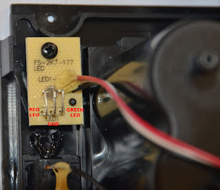
The remote LED board will be used to vampire the signal from the trap:
LED board shown with annotations
In the center of the "back" of the board I probed a good solder point to get the needed +5 and GND for my design, which I will talk about in the next post....

-----
Resources:
1. EM78P153SNJ data sheet (140-00275-0-EM78P153S.pdf)
2. The type of Bi-color LEDs used here is the type consists of two dies with separate leads for both dies and another lead for common cathode, so that they can be controlled independently.

Victor Multi-Kill Teardown

The mouse trap is very easy to disassemble. There are four screws on the front around the battery door, one screw on the front right holding the top down, and then two screws at the back along the top of the top cover.

In order to pull the battery compartment out of the trap, the lid switch lead needs to be unplugged from the back of the circuit board. NOTE: Victor did an excellent job making this repairable. Each major component is connected to the board with a plug and socket NOT soldered to board. Kudos.

Here are some close up pictures of the various parts of the trap:

Chamber the mouse goes through starting at the back left.

The circuit board is screwed to the back of the battery compartment.
The lower left shows a small PCB where the bi-color red/green LED is located.
The motor which dumps the mouse after it has expired

Several wires enter the bottom of the chamber. I did not investigate them, although one is for high voltage capacitor charging!

Next up, identifying the main components of the circuit board and the design for getting this information to an email.